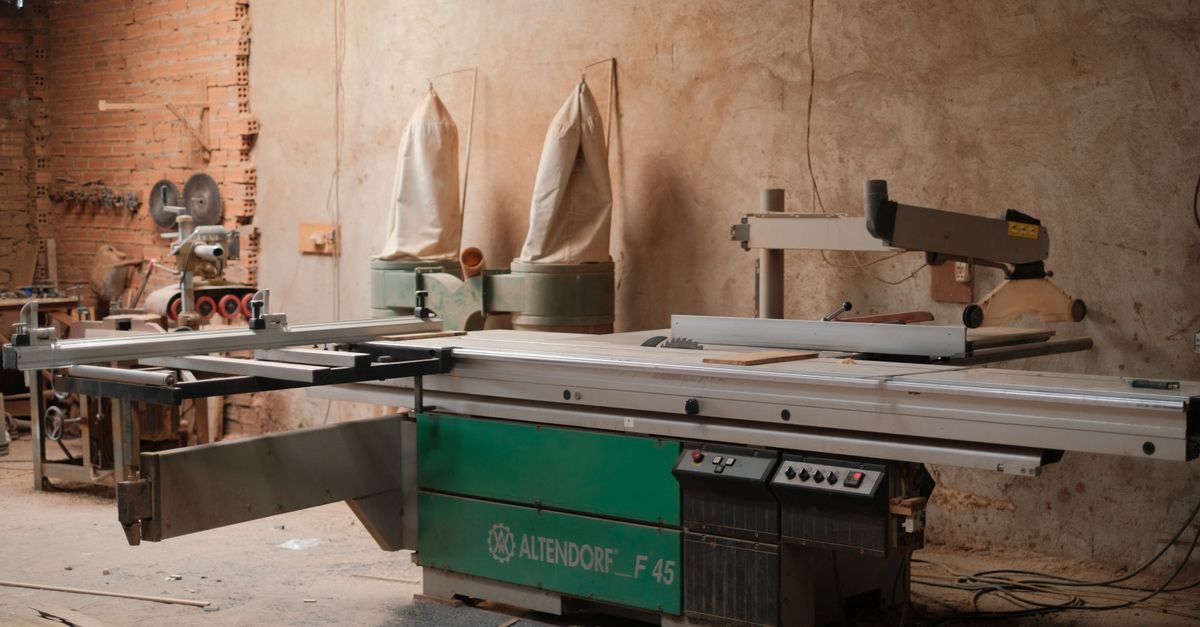
Photo: Pew Nguyen / Pexels
An extraction system has two jobs: capture the material at the process and carry it to a suitable collection system. Sizing begins with those duties and the machines that run together. Fan motor power is an outcome of the design, not a reliable starting specification.
Build a schedule of extraction points
In woodworking and furniture production, include saws, planers, routers, CNC machining and sanding. Paper and cardboard conversion may generate trim, fibres and dust at cutting and transfer points. Plastics workshops may need extraction around granulators, trimming operations and fines handling. Identify each emission before deciding which points can share a system.
| Record | Purpose |
|---|---|
| Machine, operation and processed material | Establish where capture is needed and what must be conveyed. |
| All extraction ports and manufacturer requirements | Required airflow and pressure at each connection; include ports that operate together. |
| Production combinations and operating hours | Maximum demand, low-load conditions and foreseeable peaks. |
| Scaled layout, heights and duct routes | Distance, fittings, maintenance access and future connections. |
| Particle sizes, moisture and material quantity | Transport, separation, filter duty and discharge capacity. |
| Existing system records and measurements | Check actual spare capacity rather than nameplate power. |
A port diameter does not establish its airflow requirement. Obtain the machine supplier’s data for the intended operation, or commission a capture assessment where information is missing. Air moving at a connection does not prove that contamination is being controlled at the operator’s breathing zone.
HSE guidance on specifying and commissioning local exhaust ventilation
Calculate simultaneous demand, not a convenient average
For each operating case, add the airflow required by the active ports. A branch serves its own downstream points; the main duct serves the active branches. Identify any other design air requirements separately. A general diversity factor can conceal a combination that leaves one machine short of airflow.
Check full-load and low-load cases. A restriction on simultaneous use must be enforceable through production arrangements or controls. Do not size around a restriction that the shift team cannot maintain.
Read the system as a sequence of functions
- Machines and source-capture devices
- Branch ducts serving each extraction point
- Main duct carrying the combined active flow
- Material separation and air filtration
- Collected solids discharged; cleaned air follows its designed outlet
This is a functional schematic. After separation, air and solids follow different paths. Fan position, make-up air, discharge arrangements and safety provisions require project design; they are not defined by the diagram.
Duct diameter depends on airflow and transport velocity
For arithmetic only, 1,800 m³/h equals 0.5 m³/s. At an assumed 20 m/s, the area would be 0.025 m² and the calculated diameter about 0.178 m. Selection of a standard duct size still requires system checks. The assumed velocity is not a universal recommendation for wood dust, plastic fines or cardboard trim.
Transport velocity must suit particle behaviour. Oversized ducts can allow settling at the available flow; undersized ducts can increase resistance and noise. Duct transport velocity and capture velocity at an emission source are different design quantities. Long or flexible trim may introduce blockage risks that an airflow calculation alone cannot resolve.
Specify the fan duty as airflow at pressure
List resistance through capture devices, straight duct, bends, junctions, flexible hose, separators, filters and the outlet. Actual routing matters: a short distance across the workshop can become a long duct run around building obstacles. Consider the filter throughout its intended operating pressure range.
The designer must analyse the demanding paths and balance parallel branches. Do not add the pressure losses of parallel branches as though they were all in series. Ask for the required flow–pressure duty and the selected fan curve, with the operating assumptions stated.
A larger fan can leave a poor hood ineffective, upset branch balance or overload filtration and discharge. Diagnose low performance first: inappropriate capture geometry, deposits, air leakage, excessive flexible hose, incorrect damper settings or abnormal filter resistance.
Match separation, filtration and discharge to the material
Large chips place demands on solids discharge. Fine dust places demands on air cleaning. A pre-separator may reduce the filter’s material load; it does not automatically provide the required fine-particle removal. Moisture, stickiness and abrasion can change the choice of components and maintenance arrangements.
- State the dust and chip characteristics, material loading and variability.
- Define acceptable air discharge and any proposed return-air arrangement against local requirements.
- Check filter area, cleaning method, pressure monitoring and compressed-air demand where applicable.
- Specify contained solids handling, discharge equipment and practical container changes.
- Include make-up air and the associated heating or conditioning implications.
Returning filtered air indoors needs a specific health and compliance assessment. A filter fitted to a collector is not, by itself, permission to recirculate. Requirements depend on the contaminant and jurisdiction.
Evaluate energy at the actual operating duty
Variable-speed control can be useful where active demand changes. It must preserve adequate capture and material transport in every relevant section at low load. A percentage reduction in flow does not establish a guaranteed energy saving; pressure, efficiency and the control strategy matter.
US Department of Energy: assessing industrial fan systems
Address combustible dust and fire as system risks
Some dusts can form explosive atmospheres. Material properties, fine fractions, ignition sources and operating or fault conditions determine the assessment. Where needed, dust testing supplies properties for the protection design. A competent specialist should define the measures and their location.
In the EU, ATEX includes separate equipment and workplace requirements. The applicable zoning, equipment selection and protection arrangements follow the installation’s risk assessment and local implementation. An ATEX-marked motor does not approve the whole network. Projects elsewhere require the relevant national framework.
European Commission: scope of the ATEX directives
Commission the system, then keep its reference measurements
Provide access to ducts, filters and discharge equipment for inspection, cleaning and replacement. Record airflow at extraction points, reference pressures, settings and the machine combinations tested. Check capture effectiveness as well as measured flow. These records provide a baseline for maintenance and troubleshooting.
Before adding a machine, recheck simultaneous airflow, branch and main duct performance, fan duty, filtration, solids discharge, make-up air and protective measures. Planned future connections are useful only if their eventual operating cases have been considered.
Include extraction in a complete recycling-line project brief
What to send for an initial engineering review
- Scaled workshop drawing with current and future machines, routes and clear heights.
- Machine data sheets covering every port, required airflow and pressure.
- Simultaneous operating cases, hours and material quantities.
- Dust or chip characteristics, photographs and representative samples where needed.
- Existing drawings, fan curves, measurements and service records.
- Air discharge, noise, safety, maintenance access and installation-window constraints.
MSR can use this information to identify missing measurements and study an extraction and conveying arrangement that fits the workshop. The review should connect source capture, the network, filtration and material handling before a fan is selected.
MSR extraction and conveying capabilities
Engineering studies and plant integration
Submit workshop data for an extraction-system review